For construction, the first part to be made was the wooden enclosure, which not only provided a housing for the alternator and bearings, but as a integral part of the structural rigidity of the entire unit. Constructed from 1/2" sheet plywood, the overall dimensions of the unit are 20" x 12" x 12". In order to ensure structural rigidity, the panels were fastened together using steel right angle brackets placed along the seams, which also allowed for proper vertical walls. Once constructed, a view-port was cut from the side piece so that the viewer can easily see the inner workings of the unit.
Once constructed, holes were bored in the top and bottom panels to accommodate the driving shaft and the support bearings, as well as the alternator support bolts.
The blades were constructed using Ultra High Molecular Weight (UHMW) Plastic sheeting, 1/8" thick. They were cut after tracing a flat pattern from SolidWorks onto the sheet, and then heated and bent to match the predetermined angle of nearly 90 degrees.
The holes were drilled in the sheeting along the open seam, and then were scribed onto the 1" x 1" aluminum (1/8" thick) tubing. The blades were then mounted onto the spine using 1/4-20 bolts and nuts to decrease any play in the connection.
There is a center hub in which the spine (1x1" tubing) will be secured and support the three blades. The hub is made of two 5" diameter, 3/4" thick aluminum cylinders and are connected to each other using 1/4-20 bolts. The center of each hub has a bore of 5/8" +/- .001 to accommodate the precision D-shaft (5/8" OD) which is the driving shaft for the alternator.
Once the two self aligning bearings were mounted and the shaft-hub assembly was completed, the unit was mounted in the box. Using shaft collars to ensure vertical alignment, the drive pulley was aligned on the shaft and the entire unit was tightened down.
The alternator, was next to be installed. The pulley that was placed on the alternator shaft had to be custom bored to a larger dimension to fit the smaller shaft, and then was secured using the set screw on the pulley. Once set, the alternator was installed using a 6" thru-bolt and a 6" threaded bolt and secured to existing mounting points on the alternator. To decrease any play once the belt was placed on both pulleys, the alternator was tensioned using a strapping mechanism which applied a constant force.
Once both the alternator and the main shaft were in place, the belt - a 5L v-belt - was snugged on both pulleys and the unit was set to being rotation.
The final constructed unit can be seen below.
Testing
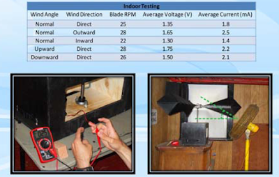
The unit was tested using a standard Craftsman Multimeter, for voltage and current production at the highest constant RPM we were able to achieve. The results can be seen below in the table.
Click to Enlarge Image
Our overall average voltage production was recorded at nearly 1.75 V at the battery terminal. The current was measured to be around 2.25mA.
Videos

